| Author |
Messages |
dannparks
Sergeant Major

Gender: Male
Location: Parkside Airpark, Battle Ground, WA
Registered: Oct 2006
Status: Offline
Posts: 391
|
      
 Posted Saturday, May 25, 2013 @ 06:03 PM Posted Saturday, May 25, 2013 @ 06:03 PM
This was part of a discussion about outrigger length a while back, and I never saw any responses.
Instead of measuring outrigger length, it seems much easier to measure the outrigger high-wheel distance to the ground and dividing it by two to get the individual outrigger wheel clearance when balanced on the main-wheel. My high-wheel distance is 4", which is only 2" per wheel when on the main gear. This doesn't seem like enough. In high-speed taxi tests it seems like the balance-point is very narrow and the wheels easily drag in the grass on the sides of the narrow paved runway and can create a side-to-side bouncing/yawing oscillation. I'm thinking the individual wheel clearance should be more like 4-5" which would make the high-wheel clearance more like 8-10".
Could I persuade some of you to make a quick high-wheel distance-to-the-ground measurement. I know there are different philosophies to the outrigger clearance issue, but I would like to get some other data (and advice).
Thanks
--------------------
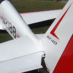
Dann Parks � RF4D #4051 N2188 � now flying!
Pictures at: https://picasaweb.google.com/111628310900713778468/RF4D_N2188?noredirect=1
|
Jorgen
Captain

Gender: Male
Location: Lund, Sweden
Registered: Apr 2007
Status: Offline
Posts: 835
|

Posted Saturday, May 25, 2013 @ 06:41 PM
Hi Dann,
that is an interesting subject and I have been quite active in those discussions since I had more than a trifle problem with it. You might recall I kept breaking my outriggers and concluded it would be smarter to have them shorter and I still think I had too long outriggers to start with. There is however another parameter I wasn't fully aware of that probably influenced my problem- the outrigger fitting angle in the fore- aft plane.
My fittings sit at 90 degree compared to the wing underside so they have a tendency to point (and bend) forward in the tail-low configuration and straight down in flying mode. This might have made my outriggers slightly more prone to breaking, which I think happens mostly due to impacts during the landing, at higher speeds and supposedly more often in crosswind. That may have been why it's been neccessary for me to shorten the outriggers more, again, if memory serves me right I have something like 30 cm highwheel-to-ground distance. Since I shortened them so much I haven't had any issues. Well, maybe next issue will be when I break the mainwheel fork due to too much sidewise load....
There is a 13 degree (if I remember correctly) rake backwards on the original fittings and that is presumably true on your outriggers, Dann- you do have the RF 5-type fitting attached to the spar, right? Remember the original RF 4 design by Ren� was wire hoops, so when we go for outrigger rods we're kind of on our own. My vote is for 30 cm (10 inch) clearance and maybe 250 hour changing intervall. In your inspiringly well maintained shop I bet you are able to find stuff, so get a rod and cut it up as spares and change every five years or so.
May the 4's be with you/ J�rgen
|
Donald
Command Sergeant Major


Gender: Male
Location: Scotland
Registered: Jan 2007
Status: Offline
Posts: 489
|
Posted Sunday, May 26, 2013 @ 04:16 AM
In 17 years I've never broken an outrigger despite giving them some abuse, including landing 'gear up'. This is not a measurement but I'd guess high-wheel clearance on my RF3 is in the order of 7-8". However I have photographs of the group of RF4's and 5's that visited Scotland a few years ago with an assortment of steel and nylon rod outriggers and the high-wheel distance I judge to range from 0" to about 10". The most original of these, with metal rods was on RF4 D-KALC and there looks to be no high-wheel distance at all.
Next time I'm at the hangar I'll take a measurement of mine and post but if it's of interest I gave Jorgen the outrigger root height in this thread http://sbeaver.com/cgi-bin/fournier/cutecast.pl?session=qiQ5psbEwPboMmxnqcHwhBhTBi&forum=11&thread=527. In the same thread Eugenio writes the high-wheel distance should be 10-15cm, 4-6".
|
Donald
Command Sergeant Major
Gender: Male
Location: Scotland
Registered: Jan 2007
Status: Offline
Posts: 489
|
Posted Saturday, June 1, 2013 @ 03:30 PM
The measurement on my RF3 is 22cm or 8.66 inches.

|
John B
Private First Class


Gender: Unspecified
Location: NE Scotland
Registered: Jul 2012
Status: Offline
Posts: 10
|
Posted Saturday, June 22, 2013 @ 05:27 PM
On the topic of outrigger legs - our RF5B has one leg which now bends too far, so that in moderate crosswinds the wheel touches the fabric of the wing underside. I presume the material has aged, though I see no sign of distortion.
What material are the legs made from please? Is it nylon? Appears to be 1" diameter nylon.
Regards,
John Bisset
|
SteveBeaver
General


Gender: Male
Location: Columbus, Ohio - USA
Registered: Jan 2007
Status: Offline
Posts: 454
|
Posted Saturday, June 22, 2013 @ 08:22 PM 
I found this to be very satisfactory:
http://www.mcmaster.com/#standard-nylon-rods/=nb5s2d
Always glad to forward stuff from US suppliers if you need.
Steve
|
Jorgen
Captain
Gender: Male
Location: Lund, Sweden
Registered: Apr 2007
Status: Offline
Posts: 835
|
Posted Saturday, June 22, 2013 @ 11:26 PM
Hi John, Steve,
since I have experience of both RF 4 and RF 5b outriggers may I suggest you use fiber-reinforced rods, John? The overhang of the RF 5b wing tends to put significantly higher stress on the RF 5 b outriggers compared to RF 4 outriggers. I tried ordinary white nylon and also polyeten rods (without fibre reinforcement) on our RF 5 b and found them both much too weak. The fiber reinforced rods I used (with satisfaction) were black and a lot stiffer.
May the 4's be with you/ J�rgen
|
Donald
Command Sergeant Major
Gender: Male
Location: Scotland
Registered: Jan 2007
Status: Offline
Posts: 489
|
Posted Sunday, June 23, 2013 @ 02:30 PM
Hello John. My stalks are nylon 66 and came from here http://www.directplasticsonline.co.uk/, but as you know, it's not an RF5.
|
Jorgen
Captain
Gender: Male
Location: Lund, Sweden
Registered: Apr 2007
Status: Offline
Posts: 835
|
Posted Sunday, June 23, 2013 @ 11:36 PM
Thanks Donald,
that's it- Nylon 66, that's what we used and it worked well on the RF 5 b.
May the 4's be with you/ J�rgen
|
dannparks
Sergeant Major
Gender: Male
Location: Parkside Airpark, Battle Ground, WA
Registered: Oct 2006
Status: Offline
Posts: 391
|
Posted Monday, July 8, 2013 @ 06:02 PM
Donald, thanks for making the measurement. It looks like I need to cut about 3" off each side.
--------------------
Dann Parks � RF4D #4051 N2188 � now flying!
Pictures at: https://picasaweb.google.com/111628310900713778468/RF4D_N2188?noredirect=1
|
Donald
Command Sergeant Major
Gender: Male
Location: Scotland
Registered: Jan 2007
Status: Offline
Posts: 489
|
Posted Tuesday, July 9, 2013 @ 01:16 AM
It might be wise to initially use the 4" - 6" figure from Eugenio as a starting point and see how that goes. It's easy to shorten afterwards but impossible to add it back on.
It's certain that Eugenio will know more about the RF4 than I do but I rather thought you'd have had more responses to pick and choose from than you have had.
|
John B
Private First Class
Gender: Unspecified
Location: NE Scotland
Registered: Jul 2012
Status: Offline
Posts: 10
|
Posted Saturday, July 13, 2013 @ 04:27 PM
Ok, this is perhaps a silly question -
Having removed the old outrigger legs from our RF5 I now need to find a way to remove, or replace, the spreader dowel into which the M8 retaining bolt fits.
Doing as the manual suggests by screwing the bolt back in partially, then tapping the end of the bolt lightly with a hammer, has loosened something, but it does not seem to be possible to remove the dowel complete. If need be I shall try to cut the top of old leg in two halves carefully to release the spreader - it looks as if the top section of the dowel may have been made as a driving fit- is there any other way to remove this, or does anyone know of a source of spare spreader dowels?
John
|
Jorgen
Captain
Gender: Male
Location: Lund, Sweden
Registered: Apr 2007
Status: Offline
Posts: 835
|
Posted Saturday, July 13, 2013 @ 05:50 PM
I know your problem John, I wasn't able to retreive the spreader dowel in a good enough shape to be useable again (RF 5b) either. I used nylon 66, and I found that standard of plastic to be good enough to drill a hole in and thread it for a bolt with deep threads. I don't know of a source for spreader dowels either, but I suppose somewhere there is.
May the 4's be with you/ J�rgen
|
John B
Private First Class
Gender: Unspecified
Location: NE Scotland
Registered: Jul 2012
Status: Offline
Posts: 10
|
Posted Saturday, July 13, 2013 @ 06:05 PM
Thanks for that Jorgen ; that was my back up plan if retrieval of the spreader dowel wasn't possible. Glad to know it works - was going to do a trial drill and threading tomorrow! It is Nylon 66 which we are using.
Regards,
John
|
dannparks
Sergeant Major
Gender: Male
Location: Parkside Airpark, Battle Ground, WA
Registered: Oct 2006
Status: Offline
Posts: 391
|
Posted Saturday, July 13, 2013 @ 06:45 PM
Gotten a little off-topic, have we  ??? ???
I cut my rods down so I now have a 9" high-wheel clearance and it seems just right. A fairly level attitude when on an outrigger. 18" of ground clearance on the down wingtip. I can balance on the main in a brisk taxi, and if I bounce off one outrigger it doesn't throw it to the other side and set off a bouncing oscillation. Thanks to all for info and advice.
--------------------
Dann Parks � RF4D #4051 N2188 � now flying!
Pictures at: https://picasaweb.google.com/111628310900713778468/RF4D_N2188?noredirect=1
|
John B
Private First Class
Gender: Unspecified
Location: NE Scotland
Registered: Jul 2012
Status: Offline
Posts: 10
|
Posted Sunday, July 14, 2013 @ 10:20 AM
Yes, slightly off topic Dan - apologies for hijacking your thread.
It was a useful and appropriate thread since our problem was excess outrigger bending and too much clearance in any sort of crosswind - in fact we were at the tip dragging stage in fairly light crosswinds with the starboard outrigger wheel even denting the wing fabric.
I have cut new outriggers some 2cm longer than the previous set to reduce our clearance. One fitted, second one to do now. Shall report back on the high wheel clearance figure, and how that works out for our RF5B.
John
|
dannparks
Sergeant Major
Gender: Male
Location: Parkside Airpark, Battle Ground, WA
Registered: Oct 2006
Status: Offline
Posts: 391
|
Posted Sunday, July 14, 2013 @ 12:48 PM
Just kidding John, no problem
It will be interesting to see what happens with your longer rods. An engineer might argue that a longer rod has more bending moment and would bend more under the same load. My shorter rods are stiffer, and feel stiffer taxiing. Yours might be more an issue of material softening over time.
--------------------
Dann Parks � RF4D #4051 N2188 � now flying!
Pictures at: https://picasaweb.google.com/111628310900713778468/RF4D_N2188?noredirect=1
|
Donald
Command Sergeant Major
Gender: Male
Location: Scotland
Registered: Jan 2007
Status: Offline
Posts: 489
|
Posted Sunday, July 14, 2013 @ 01:35 PM
Relieved you're happy with the new leg length Dan, that it's working well for you and I agree all your observations. The Plane teetering from one outrigger to the other unsettles bystanders but to me it's the norm and I like to be able to fly the wing even at taxi speed to run only on the main and the tail. It becomes a bit of a game, I find.
John you have two weeks to get that sorted out before our annual fly-in at Dornoch. Hope you and Toni can make it over.
|
John B
Private First Class
Gender: Unspecified
Location: NE Scotland
Registered: Jul 2012
Status: Offline
Posts: 10
|
Posted Sunday, July 14, 2013 @ 02:56 PM
Thanks Dan & Donald.
Dan, I agree about the length versus flexure. Our outriggers had softened and acquired a permanent bend set. The high wheel distance is now 61/2" or thereby - that does depend on where the RF5 main undercarriage decides to set. At times those gas struts appear to have a mind of their own. She should now taxi with less wing down and wobble; these legs are notably stiffer Like Donald I try to fly the wings level when ever possible. narrow runways sometimes make that a challenge.
Donald, the annual work is well in hand, with legs already done and Alan ready to double check my work this week, though I expect I will still have one dangling main door at Dornoch. Toni is making sure I have her Maus ready for Dornoch. We are hoping that she can fly the RF5 over, while I take the Grob. We shall see; let's hope this good weather is an omen. This year Dornoch, maybe next year Nevada (without the RF5, despite Toni's desire to emulate Mira Slovak!)
Cheers,
John
|
Mira Slovak
Private First Class
Gender: Male
Location: Pauma Valley Ca.
Registered: Nov 2006
Status: Offline
Posts: 13
|
Posted Monday, July 15, 2013 @ 07:37 PM
Hello John.
Great news, I have all the maps and equipment, more then happy to help. Sorry Dan.
Mira Slovak.
|
D. Porter
Sergeant First Class

Gender: Male
Location: Ventura, CA
Registered: Apr 2012
Status: Offline
Posts: 84
|
Posted Sunday, August 11, 2013 @ 04:55 PM
| Quote: |  | Originally posted by dannparks
Could I persuade some of you to make a quick high-wheel distance-to-the-ground measurement. |
|
Better late than never, I measured this when doing the condition inspection. My (original?) wire hoops put the high-wheel distance-to-the-ground at 10" from bottom of wheel.
[Edit by D. Porter on Sunday, August 11, 2013 @ 04:56 PM]
|
Bob Grimstead
Captain


Gender: Male
Location: Perth, Western Australia or West Sussex, England
Registered: Dec 2006
Status: Offline
Posts: 2029
|
Posted Sunday, October 6, 2013 @ 09:29 AM
Hiya again Guys,
From Fournier drawing No 4-42-10, the correct nylon outrigger leg length is 500mm, 50cm or half a metre.
For those of you still stuck in the eleventh century, that's 59 barleycorns, or nineteen and two-thirds inches.
Incidentally, it's interesting to see that the USA oficially defined one inch as 25.4 millimetres, no less than eighty years ago, way back in 1933. How fascinating to see that the USA's whole illogical Imperial Unit pack of cards is built on a metric foundation!
Re the rake-back of the outrigger leg fittings, that's eighteen (18) degrees from the main spar's rear face for the original wire outriggers according to drawing No 4-11-22.
Measured by protractor (there's no dimension given) the new fitting's angle seems to be identical.
Unfortunately Jorgen, that makes Mike Woollard's drawing completely wrong, so I think it might be a good idea to delete it from this forum.
We've made several fittings from that drawing, and they have all broken (both the fittings and the legs!)
The correct Fournier drawing for the later-type socket also lists part No 7, the insert at the top of the legs as a Helicoil M8. I have no idea whether the grey plastic insert I have seen replaces what was formerly a Helicoil, or whether Helicoil make plastic inserts, but I think I shall also go the way of simply drilling and tapping the legs with a coarse thread. Obviously I shall supplement this with a fore-and-aft bolt through the lower part of the socket. That bolt won't be transverse because a) that would weaken the leg in bending just at the very place where it wants to snap and a) a bolt head and nut sticking out sideways into the breeze will cause undesirable drag. ;-)
Happy Fournicating and fabricating.
Yours, Bob
|
Donald
Command Sergeant Major
Gender: Male
Location: Scotland
Registered: Jan 2007
Status: Offline
Posts: 489
|
Posted Sunday, October 6, 2013 @ 04:16 PM
| Quote: | | Originally posted by Bob Grimstead
...Obviously I shall supplement this with a fore-and-aft bolt through the lower part of the socket. That bolt won't be transverse because a) that would weaken the leg in bending just at the very place where it wants to snap ... |
|
Whoa Bob. That's surely the wrong way round.
Fore and aft is going to put a break in the tension and compression faces of the leg whereas transverse will put it right through the neutral axis and that's where you want it.
Donald
|
Bob Grimstead
Captain
Gender: Male
Location: Perth, Western Australia or West Sussex, England
Registered: Dec 2006
Status: Offline
Posts: 2029
|
Posted Thursday, October 17, 2013 @ 10:27 AM
Oops, too late.
The Australian's bolts are transverse nd they haven't broken yet.
Also I have several spare legs.
We shall see....
Watch this page.
Yours, Bob
|
eugenio
First Sergeant


Gender: Male
Location: Str. Val S. Martino inferiore 133/7 I - 10131 Torino ITALY
Registered: Oct 2006
Status: Offline
Posts: 294
|
Posted Thursday, October 17, 2013 @ 02:33 PM
The grey insert in the leg is just an expansion dowel like those used on walls, it should expand the leg onto the fitting in order to avoid the leg's rotation. This is why often removing the leg is quite hard.
Eugenio
|
SteveBeaver
General
Gender: Male
Location: Columbus, Ohio - USA
Registered: Jan 2007
Status: Offline
Posts: 454
|
Posted Thursday, October 17, 2013 @ 03:45 PM
Bob,
i used these threaded inserts designed for plastic and have had no issues:
http://www.mcmaster.com/#94510a045/=oz8uj2
I deliberately drilled the hole off-center (in both the fitting and the top of the leg) so that the leg cannot rotate in the socket. Like most products from this company, they come in a bag of <far more than you need>, so I have lots left over if you want some. Simply make the hole and tap the insert in place.
Steve
|