Reconstruction of a Bücker/CASA BU1330 for Mike Weaver, Owner/Pilot
Part I
Falling in love all over again.
We have been restoring US WWII era warbirds for sometime now. Consequently, when Mike Weaver of San Diego, CA came to us with his Bücker 133 project, we debated whether we could positively contribute towards his aircraft. The finesse and elegance of the Bücker as compared to a Curtiss P-40E Warhawk of similar epoch, which we had recently completed, was akin to transitioning from 60’s era American muscle car to 19th Century Habsburg cabriolet. Almost a year into the project, we can honestly say we have fallen in love with airplanes all over again.
Mike’s project consisted of a Joe Krybus fuselage equipped with an Experimental GNX O-360, 180HP power plant mounted on a modified Dynafocal engine mount.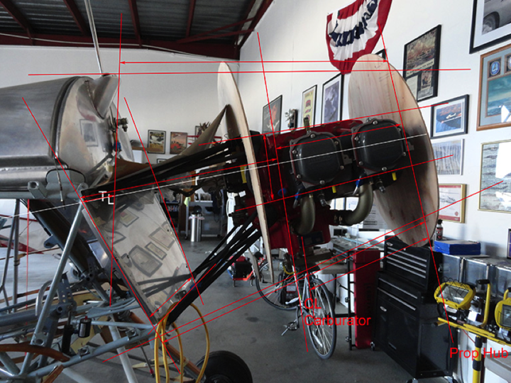
Figure 1. BU-1330 as first presented to Flyboys. Note space in between engine and firewall.
Initially, Mike sought to replicate a Jungmeister round engine cowl to adhere as much as possible to the original type design. This presented a series of challenges. In order to preserve the CG within the design range, the O-360 was pushed forward which in turn elongated the engine cowl’s profile. The conventional round cowl would thus appear “floating” way forward of the original design with an inordinate amount of empty air space in between the round cowl and the engine block and the cowl and firewall. Neither Mike nor we were convinced with the round cowl solution.
The second option Mike came up with consisted of blending the top and bottom engine cowl to a pre-manufactured fiberglass nose cowl originally designed for a Pitts Special. This option did not meet with much applause either. It simply didn’t look or flow right. The top of the nose cowl sat too low in relation to fuel tank and the curves were forced.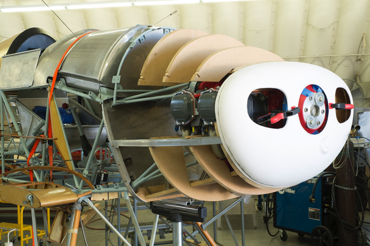
Figure 2. Option 2 for engine cowl design.
In order to support the upper engine cowl, we designed a tubular frame. From the onset, Mike requested we over engineer all assemblies. After several Warbirds, this came rather natural to us. The frame, gussets and tabs were manufactured out of 4130 Chrome molly steel. The completed frame was subsequently primed with a two-part epoxy primer and top coated with a two-part HS polyurethane.
The lower firewall was also modified. Our calculations called for additional support tabs for the bottom engine cowl frame and brackets for the battery and fuel selector valve.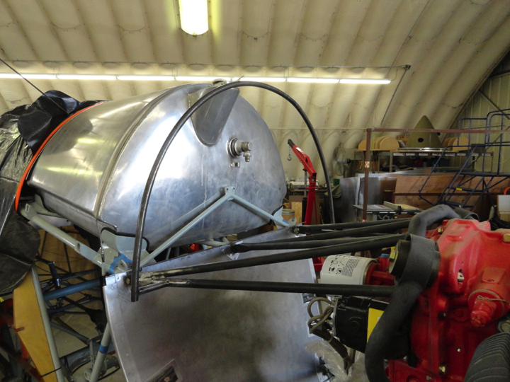
Figure 3. Top engine cowl and upper firewall support frame.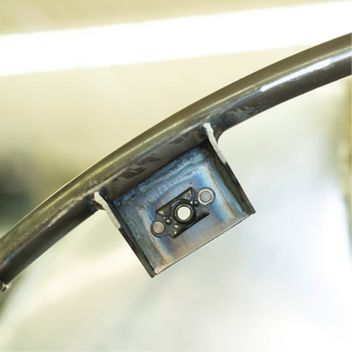
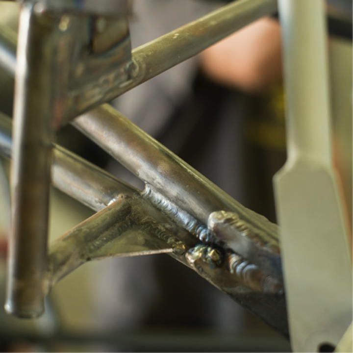
Figure 4. Typical upper frame tabs and gussets.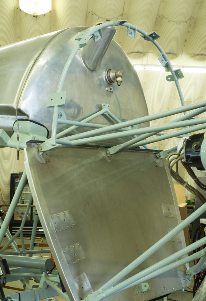
Figure 5, completed upper cowl frame.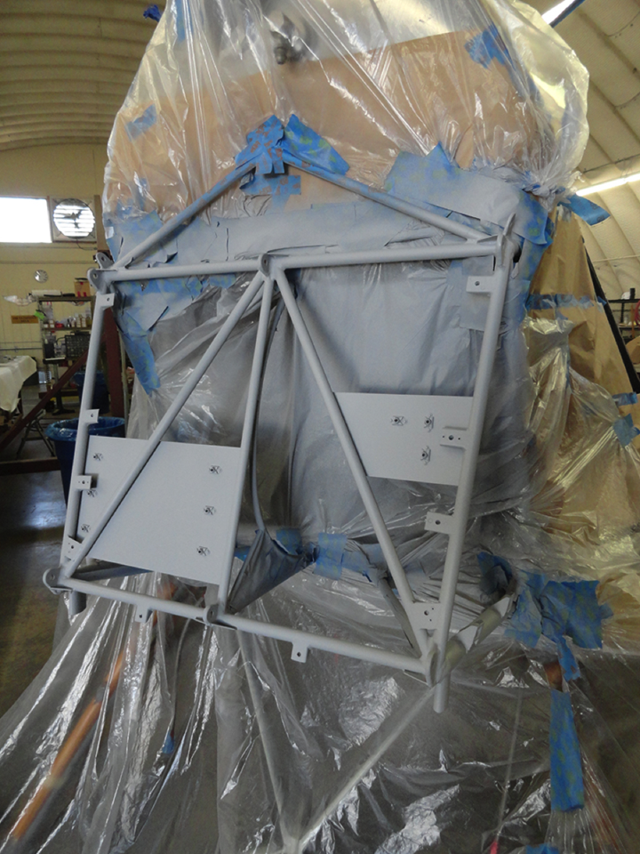
Figure 6. Brackets for battery and fuel selector valve plus cowl support tabs were added to firewall.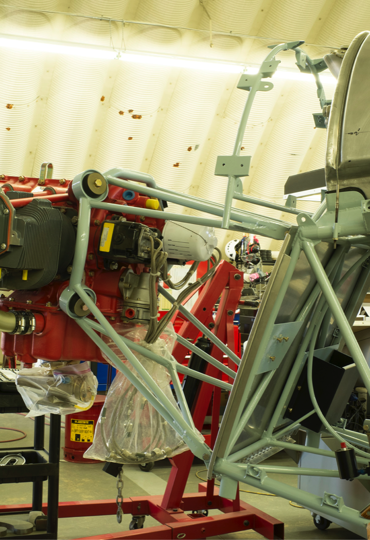
Figure 7. Aft view of modified firewall framework. Note fuel selector valve and battery brackets.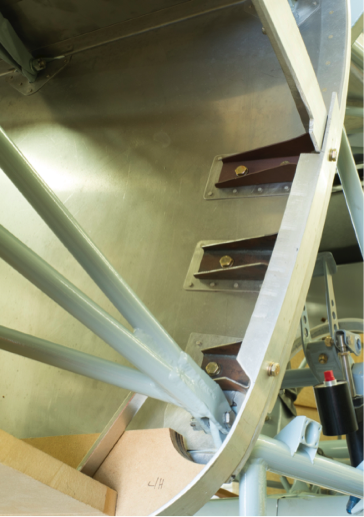
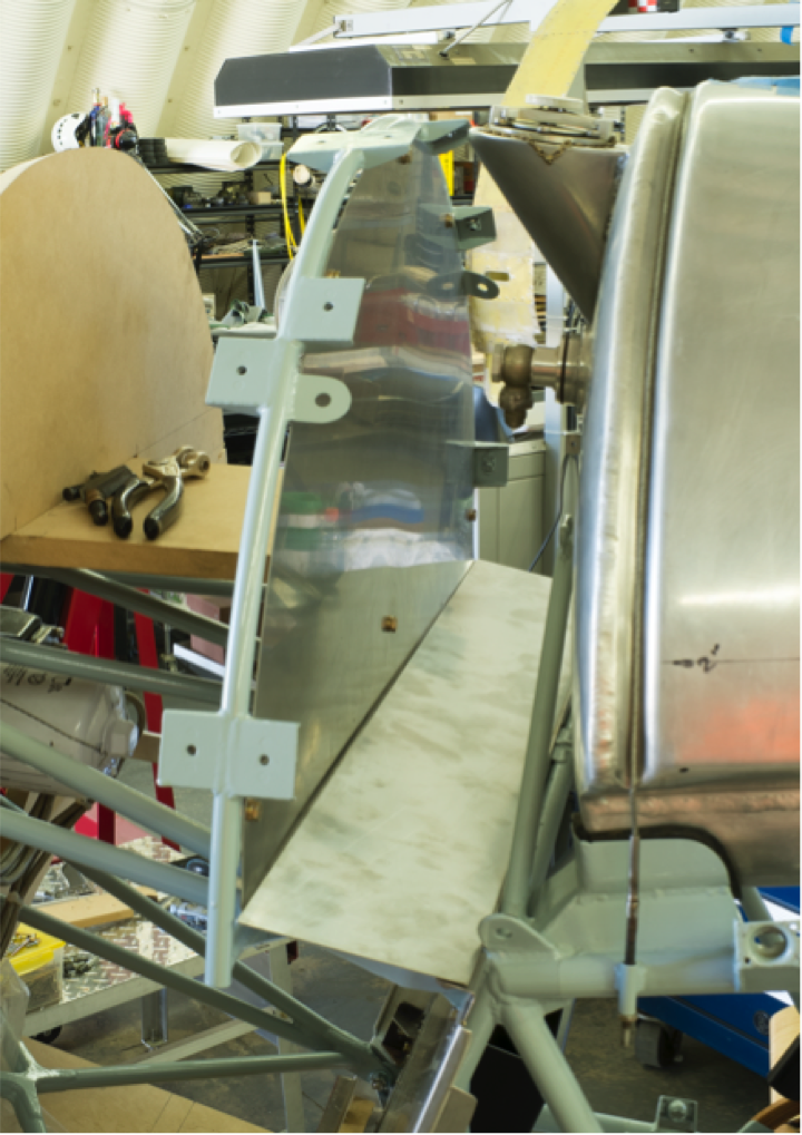
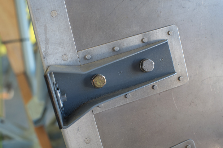
Figure 8. Reinforced engine cowl support brackets and upper firewall.
With undeterred resolve, we continued exploring additional cowl design options. The consensus was that a period appropriate nose and profile would befit the airframe most. We began by raising the nose cowl’s top edge and applied contour radiuses that were typical of 1930’s aircraft.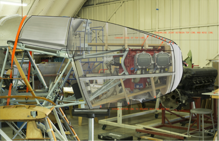
Figure 9. One of many profiles explored.
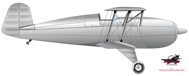
Figure 10. Penultimate profile design.
With the aid of CAD and a meticulous fabricated wood buck, we reached a profile we could all embrace, including the rest of the Bücker coven at Gillespie Field. It met the criteria for period appropriateness, elegance and aerodynamics.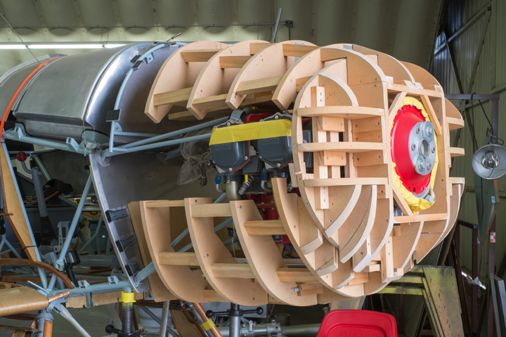
Figure 11. Wood buck shaped in accordance to final cowl design.
The cowl is being shaped out of aluminum sheet metal utilizing an English Wheel and a pneumatic power hammer. After some persuasion, Mike allowed us to explore the possibility of polishing the exposed aluminum for both aesthetics and weight savings. We have yet to weigh the cowl, but we estimate it at about 50 lbs.
The engine cowl will be comprised of six pieces. Nose, top, bottom, fuel scupper fairing and two hinged side panels. The skin has been shaped out of 3000 series aluminum sheet metal in the ¼ hard condition. The internal framework was fabricated out of 5000 series aluminum angle. We chose these series for their ability to be shaped and welded to almost any desired shape. The nose cowl alone is made up of 12 different pieces that have been welded together using mother material strips to hide the weld seams as much as possible.
It is practically impossible to hide welds when polishing aluminum. After spot polishing the nose cowl, we discovered that under certain light conditions, the welds were visible. We discussed pursuing another finish until one of the local Vintage Aircraft IAs with a couple of champions under his belt, Lonnie Bosselman, qualified our visible welds using typical Southern California parlance as “bitchin”. He said he loves them because they clearly reflect the complexity and artisanal workmanship involved in metal shaping of this nature. After hearing this, Mike gave the green light and we began the tedious but rewarding task of polishing bare aluminum. A note to anyone seeking to venture into polishing aluminum; if you are neat like us, you will arrive to work looking like a food service worker and return home looking like a coal miner.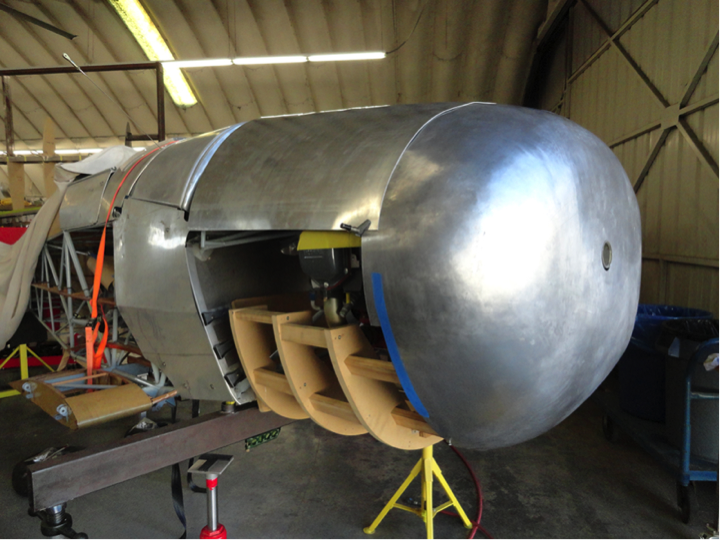
Figure 12. Two thirds into the metal shaping process.
We have also progressed with the interior of the cockpit. All surfaces exposed to high wear were powder coated for protection and the rest have been painted with a HS polyurethane. Placards have been replicated in etched brass, including the original CASA placard.
This rounds up current progress. The second chapter will cover the final fit and finish of the engine cowl and other custom features requested by Mike. I would like to take this opportunity to acknowledge my talented and hardworking wing man Danny Smith and thank John Hickam and Chris Overson for sharing their experience and talents with us.
Rolando X Gutierrez
Chief Engineer
San Diego, CA
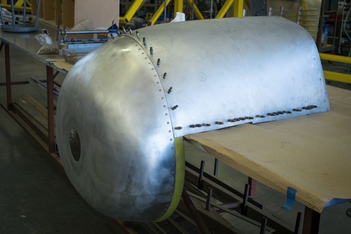
Figure 13. Nose cowl with reinforcement ring tab riveted in place and bottom cowl fitted to it.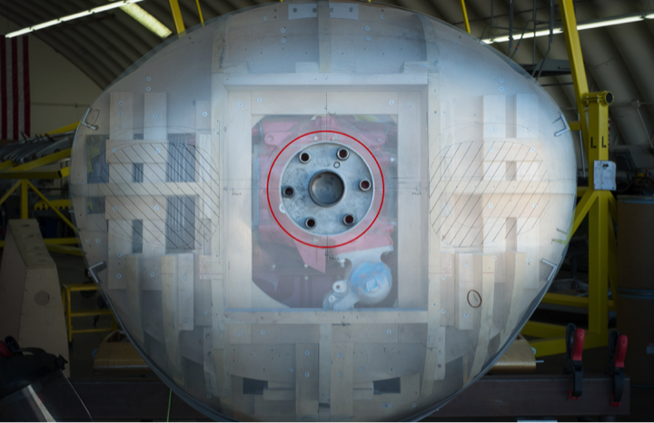
Figure 14. Determining the location of the cooling air intake openings with the aid of photography.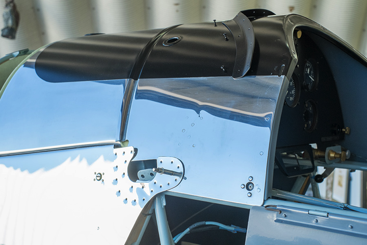
Figure 15. Fuel tank and cockpit after polish and paint.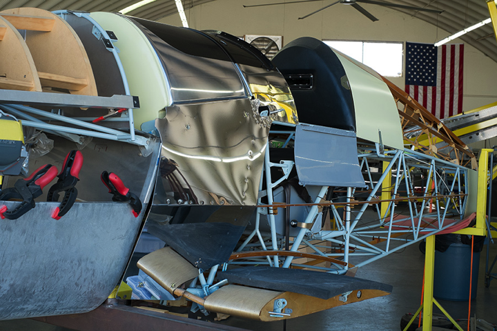
Figure 16. Cockpit side panels below the fuel tank were remade and polished. Non polished and non visible surfaces have been primed with an aerospace two part epoxy light green primer.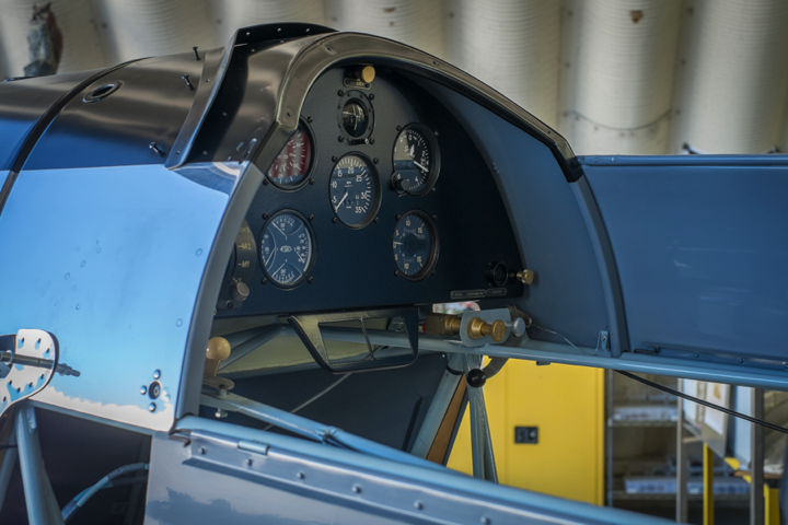
Figure 17. Cockpit interior.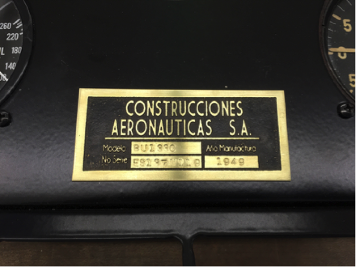
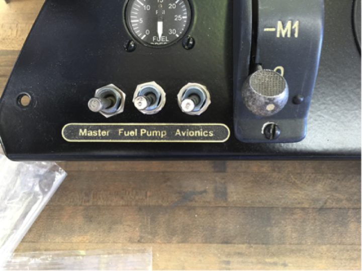
Figure 18. Etched brass placards.

