September 20th, 1980. I am leaving the college for Yvetot airfield where I expect an aerobatic ride with Lucien Canu, my chief-pilot, in his Bücker Jungmann. I began my aerobatic training a few weeks ago: half roll to inverted, half roll to erect, full roll, inverted flight, loop, and so on. Lucien takes off from the rear seat, which is the pilot's seat. Once airborne I try some aerobatic figures, flown with delectation from the front seat ,under Lucien's close and benevolent supervision. Then he is again at the stick for the approach and landing: as a matter of fact one can't see anything ahead from the front seat, I have not logged more than 40 hours, and of course his beloved Jungmann is Lucien's pride and joy.
This Saturday I find the Jungmann in single-seater configuration, her cowlings smoothly extended by a metal plate sealing the front cockpit: apparently, no aerobatics today...
But Lucien comes to me and soberly declares, as gruff as usual « I am to fly to Saint-Valery en Caux for some circuits with a trainee. I expect you there at 5 pm with the Bücker » and, without further ado, turns on his heel and walks away. There he goes flying, leaving me alone with the Jungmann. I must face the facts: I will have to do my first solo flight on my chief-pilot's plane without any briefing or support of any kind, though it is a real historical treasure - formerly owned by World Champion Lucien Biancotto, though I have never taken off or landed her at the stick, and have even never sat in the pilot's seat!
After a good period concentrating in the rear seat, the take-off eventually happens, and is unvenentful: the 180 HP Lycoming tears the plane off the ground even before I reach the full throttle stop... And there I go into the Normandy sky, savoring this extraordinary moment which, 12,000 flight hours later, still remains my best aeronautical memory. Unique controls, very light and crisp near neutral so that you hardly have to caress them, but very powerful, with few secondary effects, when you really move them. A rear seating position behind the trailing edge, which with the open cockpit provides a very airy sensation, and this uncommon feeling of almost being able, by leaning out a little bit, of grasping the ailerons or the stabilizers...
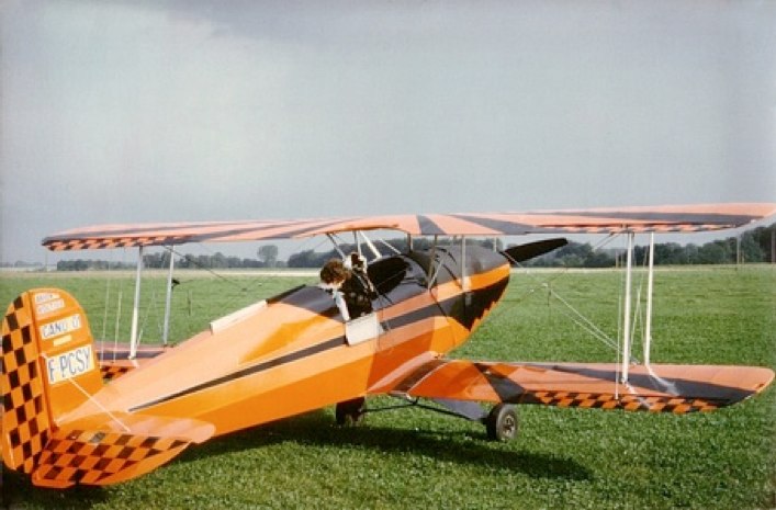
Yvetot, September 20th, 1980
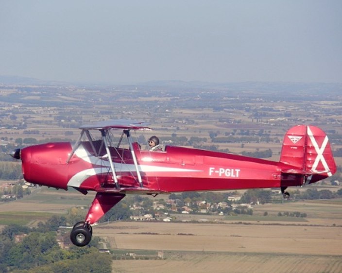
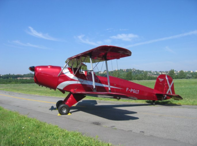
...May 29th 2008, Toulouse-Lasbordes: I am again concentrating in the rear cockpit of a Bücker for a first flight. This time the gleaming Jungmann is mine, the future F-PGLT, temporarily F-WGLT for the flight test period. Despite my apprehension of risking the result of 4 years of unremitting work, and despite my subjective confidence in the Tigre engine, which has waited for more than 30 years to once again power a plane, I will ecstatically rediscover the delights, first felt 28 years before, of flying this wonderful little biplane.
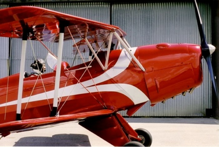
Lasbordes, May 29th, 2008
This flight is the culmination of an absolutely unreasonable adventure, unfortunately initiated through a cooperation with Jesus Ballester (Bucker-Prado) which happened to be nothing but a swindle (of which the Spanish justice since found him guilty twice).
I was relieved, however, that I could recover the parts I had provided, though Ballester didn't do one quarter of the expected work, and re-sold the good quality parts he had made for my plane to other people. Those which replaced them appeared to be discarded parts, unfit for use on a plane, and only likely to be used as models to make new ones. I will charitably spare details of the technical quality of the Spanish work as I could write a book with them. Let's just say that EVERYTHING had to be checked, and often made again, and that some of the corrected faults could have had tragic consequences. Eighteen months were dedicated to these checks.
That was a huge project, but it allowed me to build the plane that Bücker and Anderson (The A and B of SAAB) would have designed today, getting rid of the flaws linked to the 1930s technology limits. Reviving my past of Airbus designer, I began studying how to take advantage of today's coponents for better safety, and ease of operation. Out of question, of course, modifying in any way the aerodynamic characteristics giving the Jungmann such magic handling qualities that Neil Williams could qualify it as the “most rewarding light aircraft ever flown”. The structure, amazing in its sophistication, and its mechanical perfection for its time, will of course be scrupulously kept as original: my Jungmann will remain the Stradivarius of the light aircraft.
On the other hand, the « systems » can be improved by inconspicuous use of today's equipment, significantly improving ergonomics, reliability, and safety without spoiling the so specific Bücker's grace. No doubt its designer and builder, who signed such an advanced concentration of cleverness for their time, would obviously not have minded that possibility.
So, the fuselage steel structure has been welded and the engine fully overhauled in Albacete. Despite a several-decades-long storage by the Ejercito del Aire, the Tigre proved to be brand new: it had obviously never flown! All the dimensions were those of a new engine and the bronze crankshaft bearings still showed hand-polishing traces, and absolutely no trace of rotation.
The woodwork has been made with Thierry Trevel's help in Falaise (Normandy). The higher grade spruce has been glued with Sader Marine resorcinol glue. This choice first made my GSAC inspector wince because it was not mentioned as permitted glue in his booklets (last update 1985, only consisting in changing the old name « Bureau Veritas » for the new one, « GSAC »...) The problem was eventually solved by sample tests and a letter from J.M. Klinka (designer of the CAP aerobatic planes, now responsible of experimental aircraft for the DGAC). Jean-Marie testified that this glue was the only one allowed to repair the CAP 10, and build the CAP 232 structure...
A full set of stainless steel mirror-polished flying wires, made by Bruntons, completes the structure which is brand new, like the engine.
Then I seized the opportunity of missing original equipments to redesign the « systems » design for better reliability and safety:
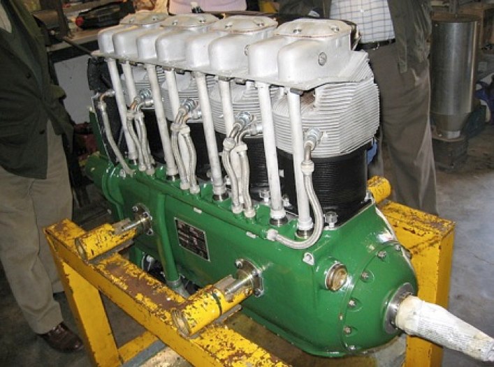
ENGINE
The Tigre G IV-B5 was delivered without the original CAT carburetor. I replaced it by an Ellison TBI which is very simple and light, and feeds the engine whatever the aircraft attitude. A throttle slide controls the airflow which is crossed by the metering tube. This tube injects fuel through a matrix of very small metering holes. The mixture is controlled by rotating the metering tube: full lean occurs when the holes are facing directly into the on-coming airflow, and a progressively richer mixture is obtained as the holes are rotated away from the zero angle of attack position. I just added a spring aimed at rotating the metering tube back to the full rich position, should the control linkage fail: some have then faced engine failure, due to spontaneous rotation to the full lean position...
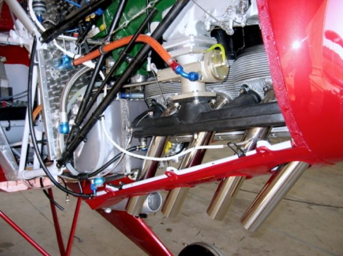
The Ellison EFS-4 TBI
I also seized the opportunity given by the TBI installation to change the mixture control to the conventional sense, rich forward: the Spaniards used it the opposite way with a ratchet linking both control levers, so that power reduction automatically set the mixture to full rich. This coupling is not suitable for the Ellison-Tigre installation, which appreciates aggressive leaning when at idle on the ground.
An Electronic International engine monitoring system provides full time scanning and recording of EGT, CHT and RPM, and triggers warnings when limitations are reached. This type of engine being rare, and spare parts difficult to find, it is wise to preserve it as much as possible. Moreover, follow-up of recorded parameters allows the anticipation of failures, and helps to avoid the unpleasant surprises encountered by some.
FUEL SYSTEM
I took particular care to make it the simplest and most compact possible: the original wobble pump at the rear seat needs lengths of intricate tubing... The small auxiliary priming tank still adds complexity, weight and frequent leaks. Sometimes 3-way-valve equipped wobble pumps lead to fuel circuits with 2 valves and 9 possible combinations, and that for only one tank! A wide open door to many problems...
So I decided to start from scratch and design my fuel circuit on sound basis, trying to avoid any useless complexity:
- The shortest possible tubing length
- Elimination of the auxiliary priming tank, the primer pump being fed by the normal circuit downstream of the fuel filter
- Only one fuel valve with 3 positions: NORMAL (gravity feed), AEROBATICS (flop tube), and CLOSED
- No tubing back and forth between the firewall and the rear seat
- Finger-strainer over the tank gravity outlet to prevent it being plugged by any foreign object
- One ultra-fine filtering stage as required by Ellison (Flow-Ezy 25 microns filter) downstream of the original filter, un-cloggable stack of 7 lenticular screens in a cylindrical bore
- Drain valve added at the lowest point in the system, ahead of the firewall
- Finger-strainer at the tank vent line tip, to prevent it being clogged by insects or their dejections
- Bleed check-valve on the vent line to prevent spilling fuel during aerobatics, though allowing heat expansion on the ground
- Back-up pump by-passing the engine vane pump, likely to block the line in case of shaft breaking. Having an electrical circuit allowed me to use a very common Facet pump placed on the firewall, instead of the unobtainable original wobble pump at the rear seat. It saved weight and money with better reliability, and ease of operation and maintenance. Moreover, this deleted 20 ft of tubings between the engine and the rear seat.
- The shortest possible length of fuel lines in the hot area, with the stand-by circuit and the Flow-Ezy filter on the cold side of the firewall, and all the tubings fire/heat-sleeved in the engine compartment.
A thorough calibration of the fuel gauge, in both ground and flight attitudes, is basic precaution: it showed that the original markings were highly fanciful, and that the real fuel tank capacity was 5 liters lower than the published value.
All the lines are made of stainless-steel-braided Teflon tubings which are light, flexible, and of unlimited lifespan. Many thanks to Michel Birello (SEEMI company) whose enthusiastic help was invaluable in their design and manufacture.
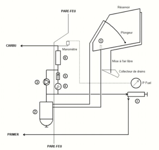
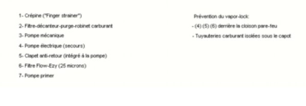
Fuel system
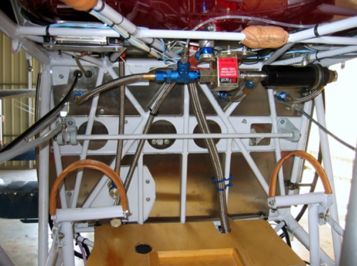
The electric pump and ultra-fine filter
IGNITION
With fuel feeding guaranteed, I took care to guarantee its ignition: the original ignition circuit showed some makeshift assemblies about which I didn't feel altogether happy...
I first replaced the old Spanish spark plugs by new REM37BY, known for allowing the Tigre a smoother running, and for their increased resistance to fouling, thanks to their better adapted threaded length.
The Spanish harness makeshift electrical contacts with the plugs convinced me to change it for a Slick harness. I just had to cut each wire to the right length and make the electrical contact with the magneto. Larry Ernewein, of Toronto, was kind enough to show me ho to proceed, and to lend me his equipment to make it. The very flexible shielded wires are easy to route and allow the deletion of the heavy, original metal shield.
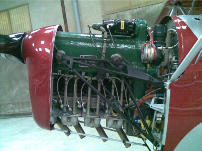
Ignition circuit
LUBRICATION CIRCUIT
The oil circuit has been entirely rebuilt of stainless-steel-braided Teflon convoluted tubing with aluminium banjo fittings. Convoluted tubing is much more flexible, particularly for the diameter involved in the oil circuit, greater than on the fuel circuit. The oil tank flop tube, in particular, is very short and must be very flexible to reliably feed the oil circuit, including upside down. The one I got from Spain was stiff as a ramrod thus unusable...
The heavy original cooler has been removed: it seems that it was only needed for the very hot temperatures reached during the torrid Iberian summers. Even in high Summer in Toulouse, the engine oil temperatures keep closed to what oil producers consider optimal.
A push-and-turn drain valve has been permanently added to the tank to preserve its drain plug’s rather tired threads (the tank is original). The same push-and-turn drain valve at the tank outlet allows one to easily prime the oil pump with a syringe: being positioned higher than the tank, the line becomes empty when the engine isn't run for a few days.
The oil tank vent design benefitted from Pete Kynsey's valuable experience and advice. Pete is Duxford Fighter Collection's chief-pilot, and long-time happy owner of a Spanish Jungmann (by the way, amid all his Fighter Collection jewels, Stephen Grey also has for personal aircraft... a Jungmann!)
So, to avoid oil spilling through the vent in aerobatic flight, the vent line is linked to the crankcase and the tank is vented through the engine breather. A secondary vent line, linked to the bottom of the tank, does the same upside down. Moreover, being made of transparent silicon, it allows one to visually check oil level, and thus to retire the oil dip-stick and its always-leaking plug.
Unlike the fuel circuit, the long oil hoses haven't been heat-sleeved to get cooling effect through radiation, and heat exchange with ambient airflow.
The last modification has been to add an easy access standard oil filter, as the original filters are only made of rather rough mesh. I not only expect less engine wear, but also easier drain operations, and the ability of taking advantage of the amazingly better performances of modern oils. Without that filter, dispersant oils, preventing micro-particles aggregation, would let them cross the mesh and indefinitely circulate through the engine...
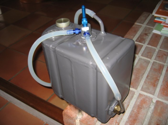
Oil tank: vent lines for erect and inverted flight
ELECTRICAL GENERATION
The TIGRE G5 accessory case offers a generator drive. The original generator is bulky and heavy, and using it on the Jungmann would require modifying the firewall and the starter orientation. I preferred using a tiny belt-driven Kubota alternator delivering 15 Amps for only 1.4 kg (3 lbs) (It is used in some starter-alternator kits for Jodels). I just had to make a drive pulley fitted to the rear drive: its size keeps it compatible with the starter and firewall. (Many thanks to Denis Bastien, of the MDO company, who kindly designed and calculated the pulley and its drive...)
The alternator as such is positioned on the left side of the engine, on a bracket fitted to the rear case studs.
The belt is a PowerTwist one, made of oil-resistent elastomer links. The belt length can be precisely adjusted by modifying the number of links. Contrarily to a continuous belt, this assembly of elastomer links is vibration damping, which advantageously replaces a torque damper.
The belt tensioner was once removed from the defunct washing machine... until I eventually found it unnecessarily bulky and heavy, and decided to make a more suitable one.
The alternator regulator is positioned on the cool side of the firewall.
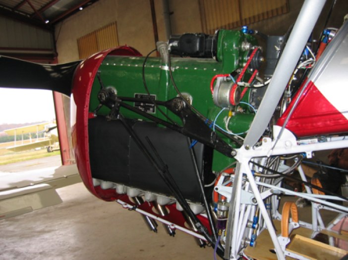
The Kubota alternator (regulator behind the mast)
This tiny electrical generator continuously feeds the transmitter, transponder, GPS, and the engine instruments. The battery is then sized for its cranking power only: two tiny Odyssey batteries of only 8 Ah and 2.7 kg (6 lbs) but delivering 310 amps cranking power, have proven to be more than enough.Moreover they can be used in any position. That's the end of the 45 lbs of battery behind the pilot's spine, rapidly leading to communication failure after exhaustion from engine start... and very badly positioned in case of crash.
These batteries are connected to the starter by an AWG4 gauge copper-clad- aluminium cable, which with almost the weight of aluminium, has copper's conductance and connection qualities. Weight saving is significant as the batteries must be positioned behind the pilot for balance reasons (the Tigre is a heavy engine!)
ELECTRICAL SYSTEM
The electrical system is dual voltage, 12v and 24v. Bucker-Prado having promised a 12V starter, the circuit was designed, and the equipment bought accordingly. But despite Ballester's promise, the delivered starter happened to be a 24V one.
Rewinding it to 12V appeared impossible, and changing the motor far from easy. The easiest and safest solution was to use two batteries. They are connected in series for start through a guarded toggle-switch, feeding the starter in 24V. Once the switch off, they are connected in parallel and the starter circuit is no longer connected: the start push-button is deactivated, which provides ground safety. Difficult, indeed, to prevent onlookers from fingering in an open cockpit...
The weight penalty is eventually limited if any, as two 6-lb batteries are more than enough, thanks to the AGM (absorbing glass material) technology: their very low internal resistance gives them a tremendous cranking power, and they accept fast charge. During the engine tune-up phase, I spent days starting the engine, running it for a few minutes, stopping it for some tuning, then starting it again. At the end of the day, the small batteries, having been charged only a few minutes by the tiny 3-lb alternator, still easily started the 150 HP Tigre.
Once connected in parallel, the battery charging, as well as their connection to the aircraft bus, is managed by a featherweight battery separator such as you can find in multi-battery recreational vehicles.
The rest of the circuit is of simple design, as the plane flies perfectly without any electrical power: losing the radio or the engine instruments is no emergency flying VFR...
The circuit design benefitted from Gérard Mercadier's enthusiasm and experience: Gérard usually practices his skills on the Armée de l'Air planes and helicopters, so the wiring complies with current military standards!
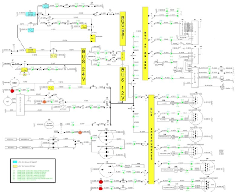
Electrical wiring
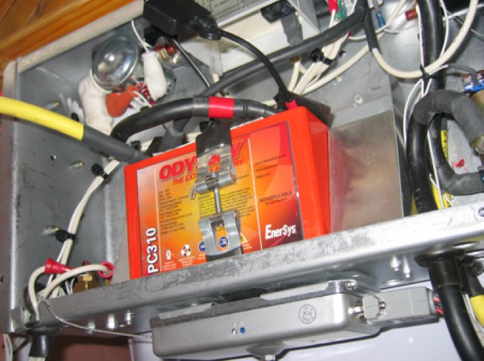
Odyssey PC310 battery
COMMUNICATIONS
Transmitter and transponder, of course: two Becker units positioned on a right side sub-panel to visually separate their LCD displays from the instruments panel, for which I wanted to preserve a classic look. Incidentally, the same position is now used on most airliners.
A matching panel on the left side gets the electric pump switch (it was originally the lcation of the wobble pump) and the engine start push-button, as well as a few circuit breakers.
A Sigtronics intercom advantageously replaces the original ear trumpet and tube... its squelch isolates engine noise while keeping a hot mike, thus avoiding a dedicated switch. Wearing Gibson & Barnes ANR headsets, the result is good so long as you avoid leaning into the airstream... then comes Hell!
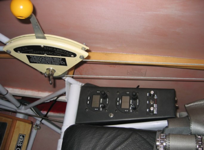
COM and electrical pedestals
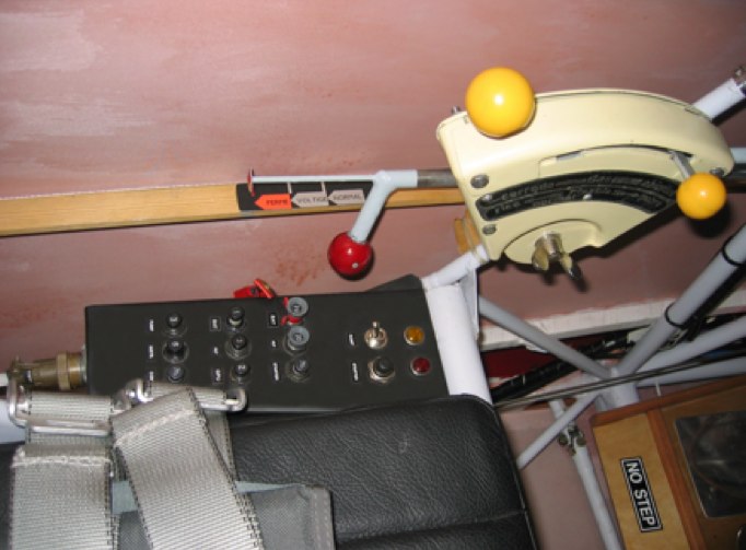
ANTENNAS
Despite up-to-date communication systems I wanted to avoid at any price the anachronistic image of a 1930s biplane bristling with numerous antennas.
Hiding the GPS antenna in the wooden turtleback, just under the covering, was easy.
The shark fin drain duct has been used to camouflage the transponder antenna: all the drains having been removed to the rear of the fuselage to keep it clean, and preserve its covering, the aluminium sheet duct became useless; I used it as a mold to make a fiberglass one which became a transponder antenna fairing, ideally positioned under the front fuselage.
The VHF antenna caused more difficulties: some place it upon the fuselage, where it is conspicuous. Others place it under the fuselage but it is still visible. Moreover I felt a little bit uncomfortable thinking of an antenna radiating just below the pilot's genitals (mine, that is). So I tried to place it in the wooden turtleback, halfway between the metal tail feathers and the barrier of the luggage compartment metal door – which also moves it away from the pilot.
A standard whip-style antenna would have been too long to keep inside the fuselage, except being bent at 90 degrees along the metal structure, which didn't suggest good performance. The solution came from Bob Archer, former NASA specialist of integrated antennas (imagine an outside antenna when a spacecraft comes back to the atmosphere...) Bob sells an antenna made of aluminium sheet, approximately A5 sized, initially designed to be placed inside the Bonanza vertical tail tip fairing. It weighs nothing, and is small enough to be easily integrated in the Jungmann's wooden turtleback.
All that is absolutely invisible and works perfectly, with even a surprising communications quality in such a noisy environment. As Bob Archer assured me, the aluminium powder protecting the covering from UV-related damage has no influence on RF radiation at VHF or GPS frequencies – contrarily to what a prevailing myth still says.
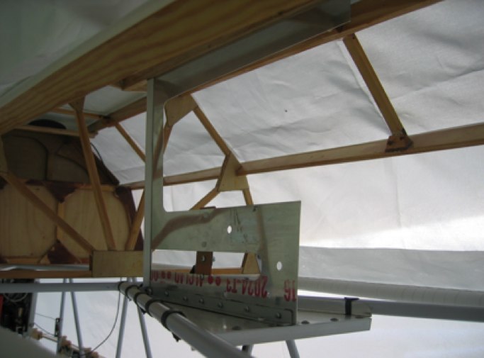
VHF and GPS antennas. No one visible antenna!
INSTRUMENTS
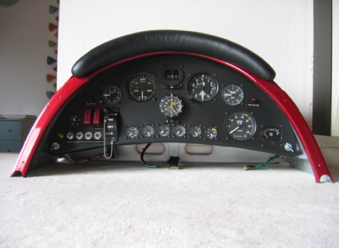
The front cockpit is simply equipped: airspeed indicator, altimeter, tachometer, compass, sideslip indicator. I did not install the fuel valve and mags controls, seeing no need of allowing my passengers to inadvertently shut down my engine.
The pilot's cockpit is more thoroughly equipped: primary flight instruments (airspeed indicator, altimeter, tachometer) are 3-1/8'' ones. The secondary instruments (vertical speed indicator, G-meter) are 2-1/4'' ones, and the engine instruments (one for each limitation, plus EGT and ammeter) are 1-1/4'' UMA instruments, electrical (but of course having a classic dial) and linked to senders ahead of the firewall. Therefore, no more fuel or boiling hot oil leaks in the cockpit. Another benefit is that it is far easier to discreetly route wires than fluid hoses.
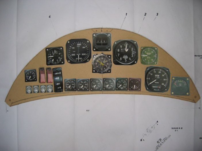
The panels layouts proceed from a thorough modeling with cardboard templates and full size pictures of the instruments and conform to some basic principles:
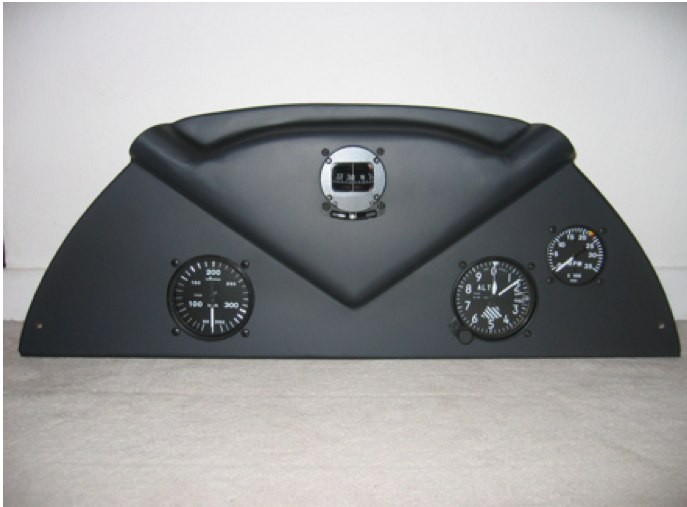
- Compass just in front of the pilots, as high as possible without being partially hidden by the leather bumper. For the front compass: as far as possible from the rigging wires which closely surround it, and sometimes prevent its compensation, making it unusable (so, I was able to compensate it with a 2 degrees mean error)
- Airspeed indicator and G-meter on the left, altimeter and VSI on the right
- Clock and sideslip indicators in the middle
- Tachometer on the right side as was the original, as well as carb temperature (same side as the carb heat control)
- A micro electric panel in the left corner includes the magneto selector, the 24V engine start configuration guarded switches (on either batteries or GPU), the ammeter, and the alternator warning light, plus the switches: Master, Alternator, Avionics and Tachometers. The tachometers (though having classic dials, of course) are electronic and simply connected to the magneto selector to count their impulses. Their installation is very simple, much easier and much more reliable than the original ones, which required the routing of a rotating cable from the engine to the rear seat with a take-off to the front seat, and angle drives preventing any flush installation on the instrument panel: they were unpleasantly positioned on an angled bracket, close to the pilot's face. Add unstable indications, notorious inaccuracy, and frequent failures... all flaws cancelled by the electronic instruments, simply connected to the magnetos selector via a switch allowing to get RPM from either mag1 or mag2, otherwise a mag test wouldn't be possible! Moreover, I took this opportunity to use a 3 positions switch, the third one disconnecting the tachometers from the magnetos just in case one of these instruments would stupidly happen to get grounded, also grounding the magneto it is connected to. You never know...
- Separation of fuel and electricity: electrical panel and instruments supply on the left corner, primer syringe and fuel lines on the right one.
- Modular instrument panels, easily taken out by disconnecting 3 plugs: supplies, grounds, senders. So much easier to work at home...
- Two red lights warning the pilot of the potentially dramatic situations at taxi or landing: unlocked tailwheel or locked park brake, likely to cause ground loop or nose-over... Both red lights also simultaneously flash when engine limitations are reached (RPM, EGT, CHT cooling rate ) thanks to the analyzer.
The UMA CHT indicator unfortunately happened not to be temperature-compensated, the instrument supposedly being at a constant 20°C. Any difference leads to an opposite CHT reading error of the same value. Thus hot summer conditions can lead to a CHT reading lower than reality, of 10,15 or even 20°C, precisely when a thorough and accurate monitoring is imperative. Jean-Pierre Castiello, great soaring pilot and electron tamer, cleverly built a compensation interface with the microchip used for measuring the A320 brake temperature, and some Concorde spare parts still hanging out in his drawers.
Modelling the pilot instrument panel
Pilot and passenger instruments panels
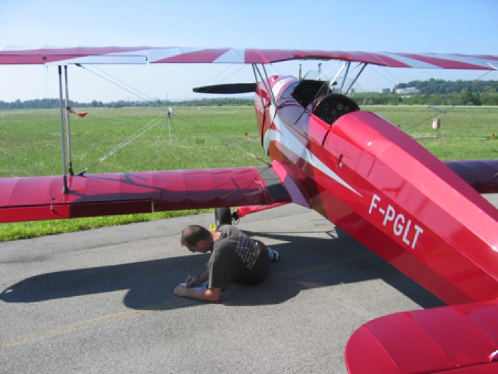
Calculating the compass compensation (using the marker in the grass)
PROPELLER
The original Spanish propeller is notoriously unsuited to the 150 HP Tigre, the torque curve of which differs from the 125 HP G IV-A2 used on the CASA Jungmanns. So equipped, it hardly develops more than 100 HP at take-off, with dramatically low RPM and obvious overtorque.
After exchanging a few mails with Batala who now builds it in Zaragoza, I still didn't feel confident with their ability to adapt this propeller to the upgraded Tigre version. Richard Evra, of Creil, did it with enthusiasm and success: his prop, magnificent with its metal shield perfectly integrated in the airfoil, provides the expected RPM at take-off and beyond compare climb performance.
The spinner received from Spain would obviously not have survived even a ground test at idle: I had to make a new one. An Airbus subcontractor spun the raw shape, but he was desperately puzzled about how to make the scoops allowing the Tigre breather to perform through the crankshaft.
Jean-Baptiste Travers, homebuilder of a wonderful JPM-03 Loiret and real wizard of material, was able to design and make the tools to complete the spinner.
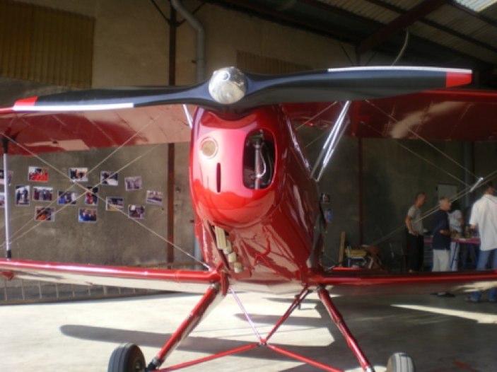
The Evra propeller and the breather-spinner
WHEELS AND BRAKES
The original bearing-less wheel shafts rapidly take play, and their cable-controlled drum brakes are poor, and must be frequently adjusted. I tried to replace them with small hydraulic disc brakes, provided that they can’t be seen: the Cleveland brakes commonly used in the US are rather conspicuous. Mr Denis Bastien, of MDO company (Biarritz), upgraded his ultralight wheels to light aircraft wheels, which fully met my specifications: a tiny disk is integrated flush to the rim, bolted at its outside diameter. The caliper clutches the disk over its inside diameter, so that only a half-caliper protrudes out of the wheel.
These wheels rotate on two thoroughly sized conical ball bearings, and their ultralight aircraft origin keeps their weight to a minimum, material having been added only where needed. Their tubeless design also spares the weight of two tubes.
The Matco master cylinders gaskets being only DOT3 compatible, and the caliper ones only DOT4 compatible, I eventually solved the problem with the DOT5.0 silicon brake fluid, compatible with any kind of gasket.
Rather difficult to find (not to be confused with the common DOT5.1) and more expensive than vintage Champagne, it is in a Harley Davidson shop that I found it in reasonable quantity and price.
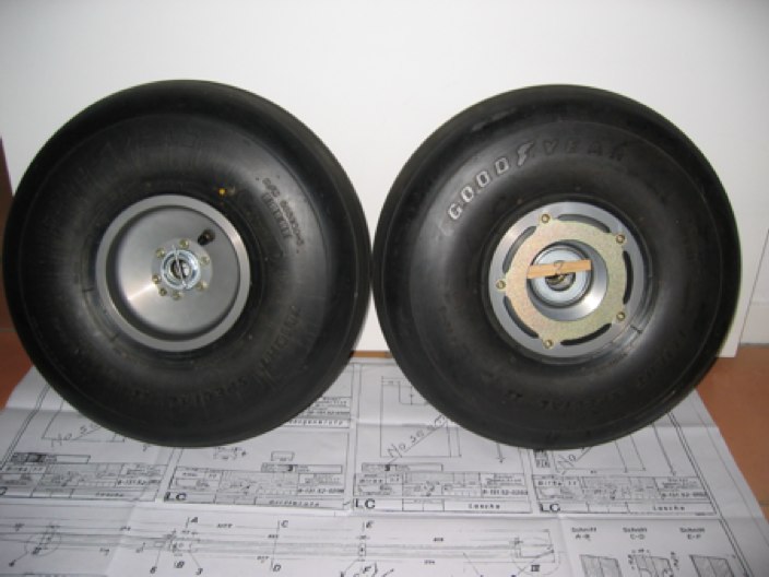
MDO R66 MK III wheels
HARNESS
Hooker harnesses seduced me by their comfort pads and the exquisitely vintage look of their lever locks.
Their ratchet allows one to tighten them easily, even flying inverted. They are not TSO’d but never get loose, contrarily to some TSO’d more expensive ones. Each of the 7 belts can sustain 1,500 lbs and the hardware shows obvious sturdiness. On the other hand, they are undoubtedly heavy!
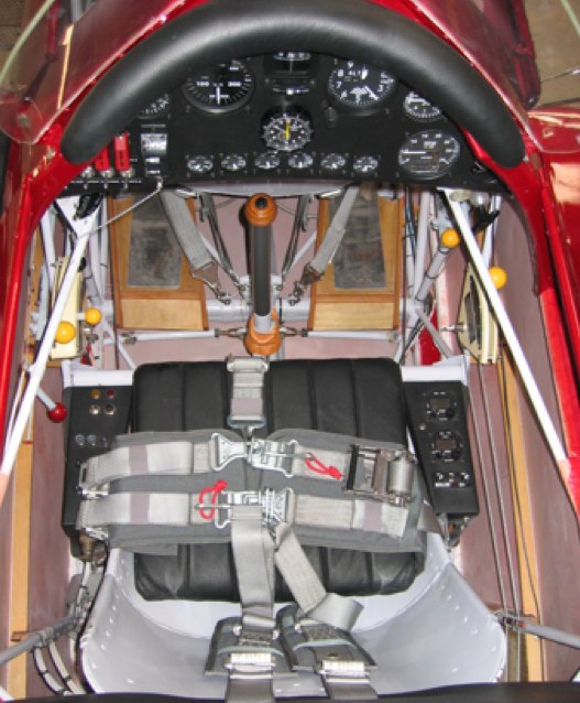
Hooker harness
FINISHING
Covering was made with Polyfiber vinyl products, which become self-extinguishing once the solvents have evaporated.
I couldn’t thank as much as they deserve: Jose and Soledad Messeguer who were kind enough to accept me getting get them from Albacete to Toulouse for covering, despite the language barrier and an age that makes travels difficult... moreover, during the 2006 year end festivities!
Jose has been for 47 years the head of the covering workshop in the Albacete Maestranza. There he had constantly covered, and covered again ALL the Spanish Bückers with Sole, seamstress at the workshop... until their wedding made her leave her job: Franco’s dictatorship then didn’t accept married couples together in the civil service.
They are so experienced that they could cover a Bücker eyes closed in no time, with an outstanding care. They did it in the Airbus aero-club maintenance shop, thanks to Denis Oswald and Jean-Philippe Grandvaux’s generous hospitality.
Jose and Sole’s stay at our home was a pure delight, and we had tears in our eyes when they left.
A polyurethane plasticized paint, metalized and varnished, gives a well-groomed finish matching the covering work quality.
Many thanks to Luc Renault for his faultless spray gun mastery and his fussy attention to detail, and to Bernard Desmoulins for giving us access to his painting booth.
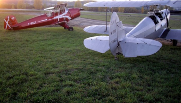
With the Stampe at sunset
EPILOGUE
The Jungmann Lima-Tango now flies perfectly and, despite very cautious tests and fine-tuning, 25 hours were flown last summer. The investment in time and reflection paid off: in a few months we achieved a technical stability comparable to, if not better than can usually be obtained after several years of predicaments and frights on Spanish Jungmanns.
The Tigre still suffers a few oil leaks, and I expect to replace the faulty gaskets at the next oil change: the quality of the mating surfaces is obviously far below current standards...
As well as a fascinating technical approach, this building first was a very beautiful human adventure: a fantastic worldwide cooperation, thanks to the internet especially, quickly helped to forget a few treasons.
So, many thanks to Steve Beaver, administrator of www.bucker.info website, and to all the enthusiasts from all over the world, Americans, Austrians, Canadians, Englishmen, Frenchmen, Germans, Spaniards, Swiss who all offered valuable advice and generous help.
Thanks also to the members of ACAART, association of talented homebuilders in Toulouse who so often offered their technical skills and human qualities.
Finally, thanks to all those who on countless trivial or essential occasions gave me a hand without which this project wouldn’t have come to an end.
And, very obviously, I must thank and congratulate my wife Corinne and my children Axel, Mathias and Maïlys who held out during this rather uncomfortable period!
After all is said and done, the lesson I learned from this experience is that one can encounter as much professionalism among «amateurs» as amateurishness among so-called «professionals»!
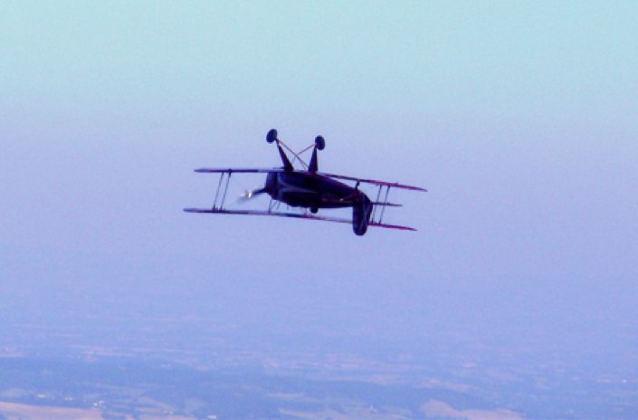
Fly a Jungmann...
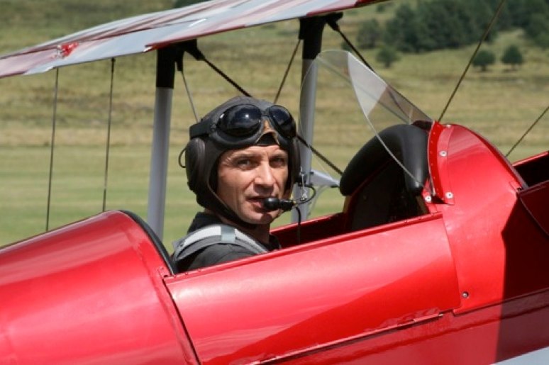
Author Gilles Tatry

