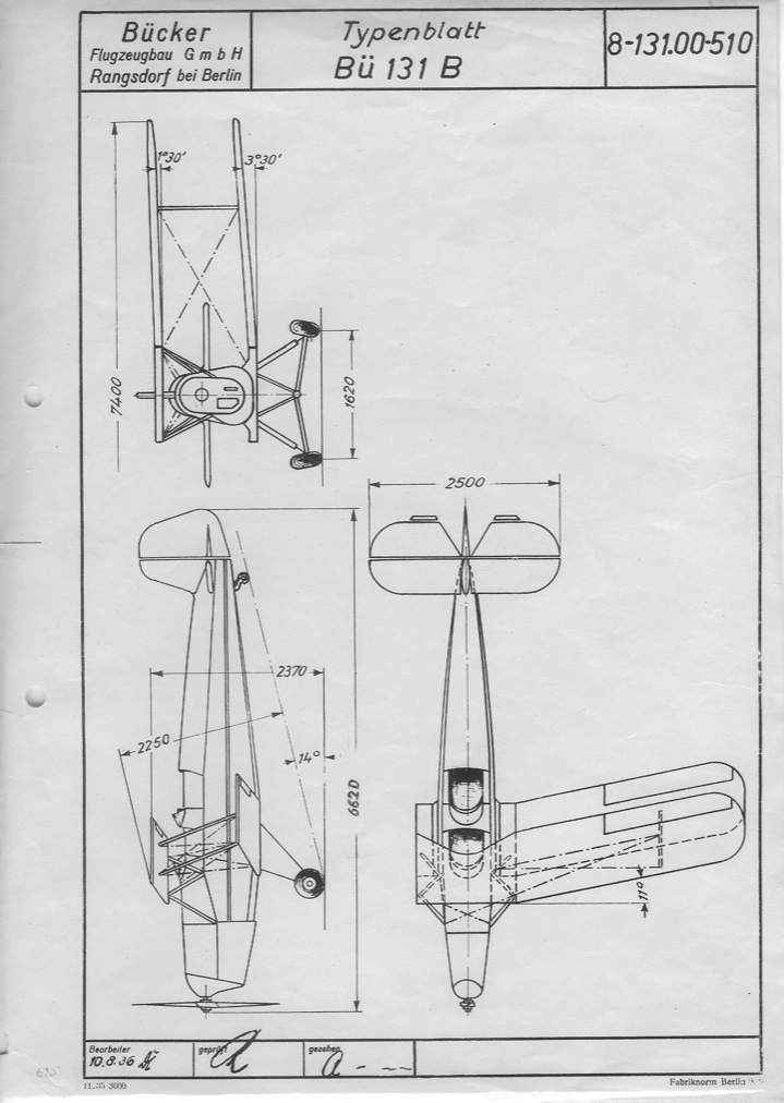
This page is a compilation of material gathered from Old Bucker Club newsletters, the CASA 1.1131-E manual and other sources.
Newsletters 1, 4 and 53 each list the flying/landing wire tension as "90 to 136 pounds". Elsewhere, an article by Earl Hickman lists 550 pounds, and this corresponds to the figure in the CASA manual exactly.
Where does that 90 to 136 figure come from? - I really don't know. The numbers on this page are from the CASA manual.
Let's start with official word from CASA:
Procedure (from the newsletters):
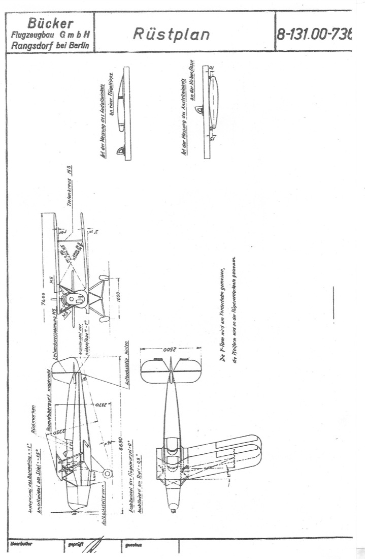
The old newsletter articles explain how to set dihedral and incidence using a bubble level and a ruler. Today, we would use a digital level to get all the angles right. The underside of a Bucker wing is just about flat, so all measurements are made by using the underside of a representative rib.
In newsletter #1, it was claimed that a Jungmann can be rigged in 30 minutes. - Good luck with that :)
The process is not at all difficult, but the order in which the wires are installed and tensioned is critical:
- Top center section
- Landing wires
- Incidence 'X' wires between the interplane struts
- All other wires
The first order of business is to assemble and rig the upper wing center section. Since the cabane struts are of fixed length, the only adjustments to be made are lateral. After leveling the aircraft using the three level points in the rear cockpit, inset a long dowel or drill rod through both the front and rear lower wing attach fittings on each side of the fuselage stub-wings. Now drop a plumb line from the upper wing attach fittings. The cabane wires should be adjusted such that the plumb lines dropped from each of the four upper wing attach fittings exactly line up with the center of each dowel/drill rod.
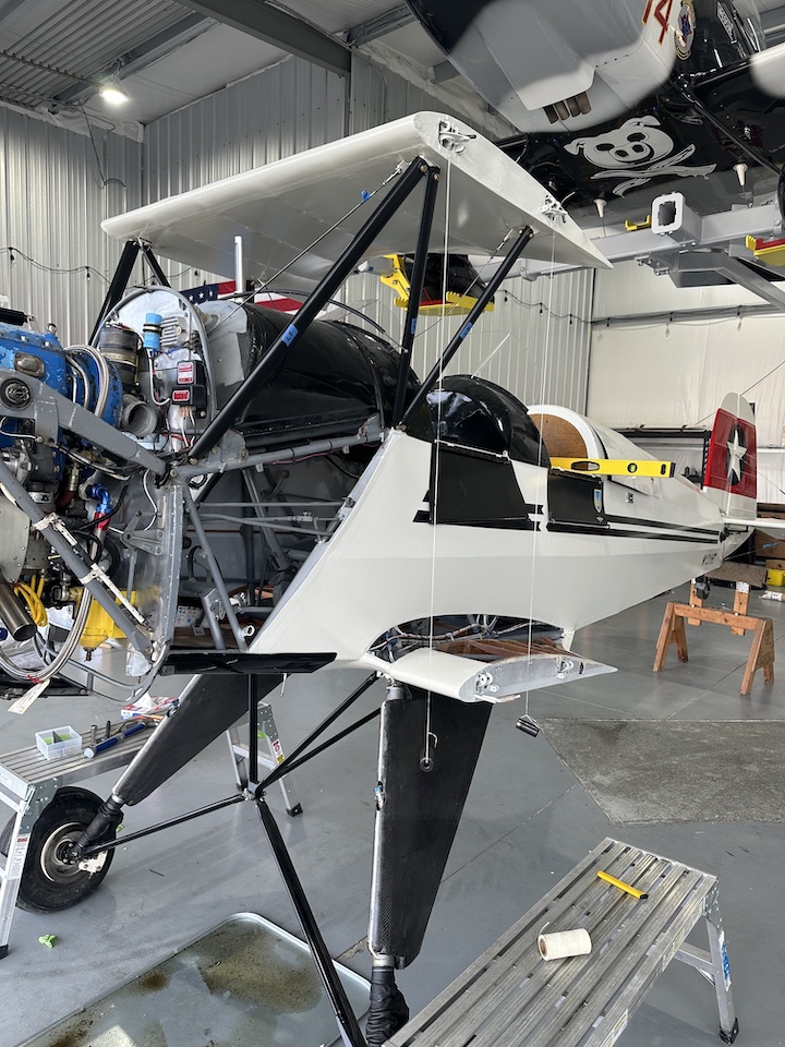
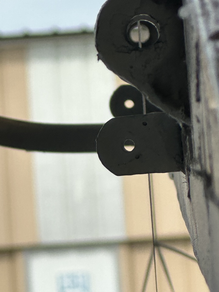
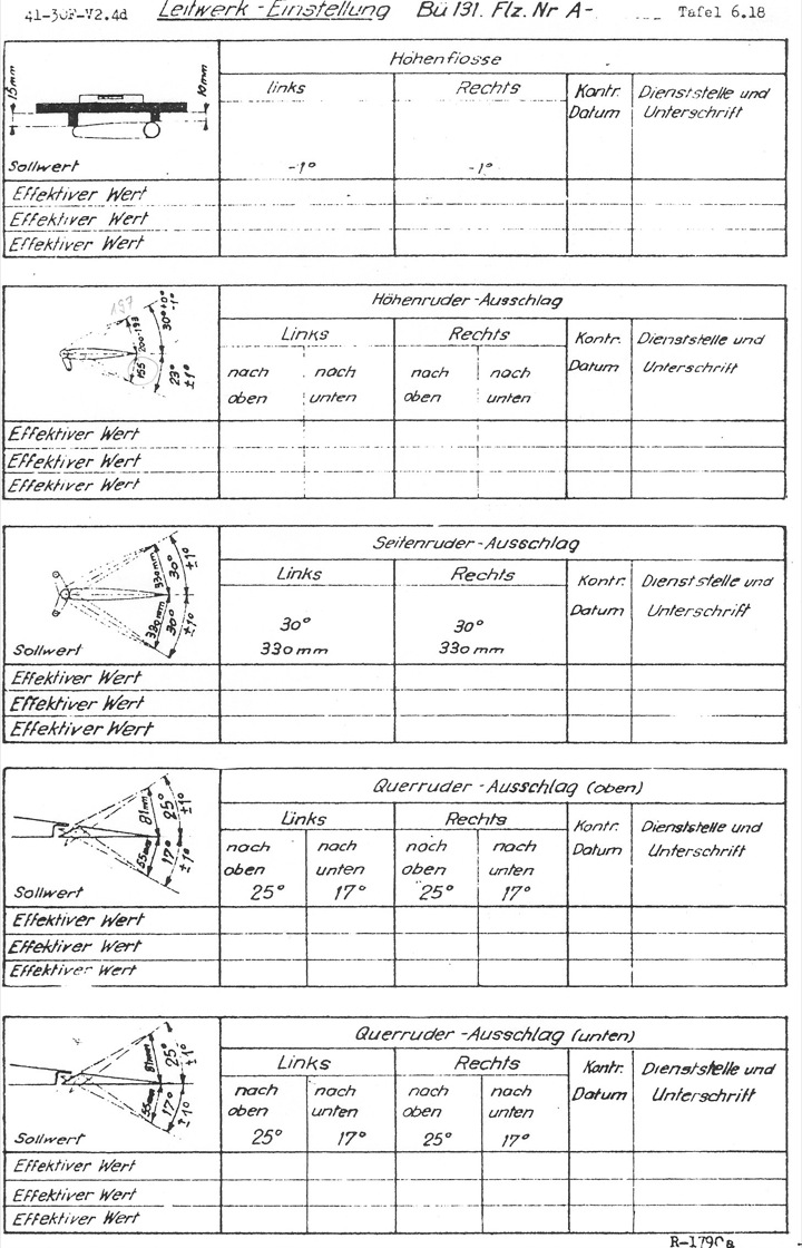
After the wings are installed a final check can be made by meauring the distance from each upper wing tip to the top of the fin.
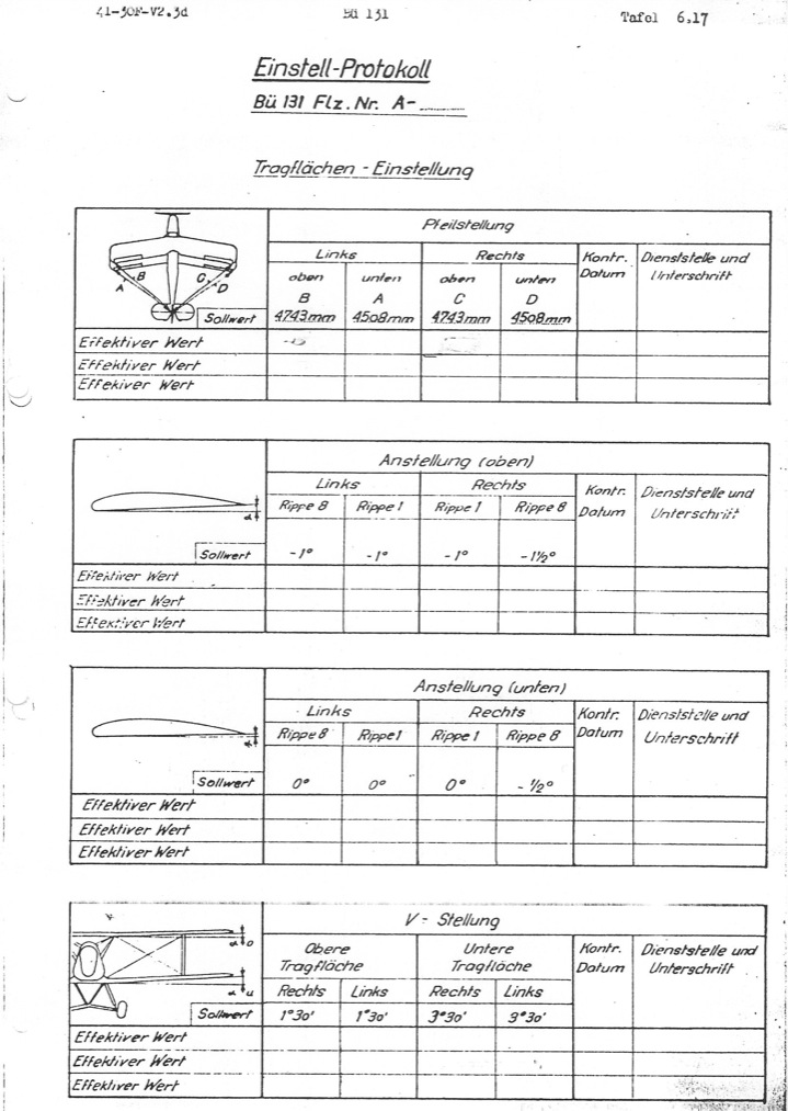
After the center section is rigged, check the angle of incidence. It should about -1.5 degress +/- 0.5 degrees. The lower wing stubs should measure about 0 degrees.
Now the wing panels can be attached. First install a bottom wing using the pins at the root, supporting the tips on a convenient stand. Now install an upper wing, using small diameter temporary pins at the wing root so that it can move around a little. Next install the interplane struts. After they are installed, remove the temporary pins and install the real pins.
The landing wires should now be installed. Set the dihedral of the lower wing to 3.5 degrees by adjusting the landing wires.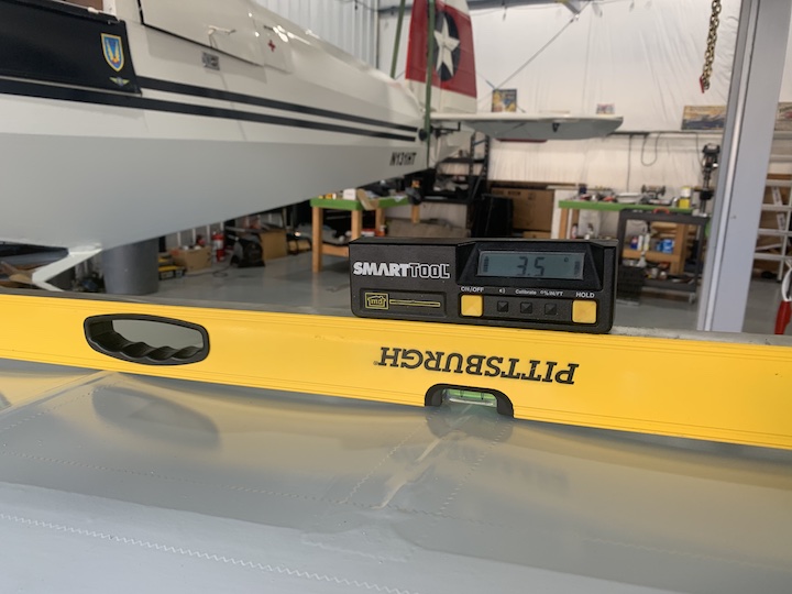
Now adjust the wing incidence using the 'X' incidence wires that connect the top and bottom of the interplane struts. Simply measure the angle of incidence on the underside of the wing at the root, then adjust the incidence wires until exactly the same angle is measured at the tip. Ensure that the flying wires are loose before adjusting the incidence wires. You don't want to be fighting the tension in the flying wires with the much smaller incidence wires. Depending on the engine in use you might rig one side about 0.25 degrees LESS negative to compensate for torque.
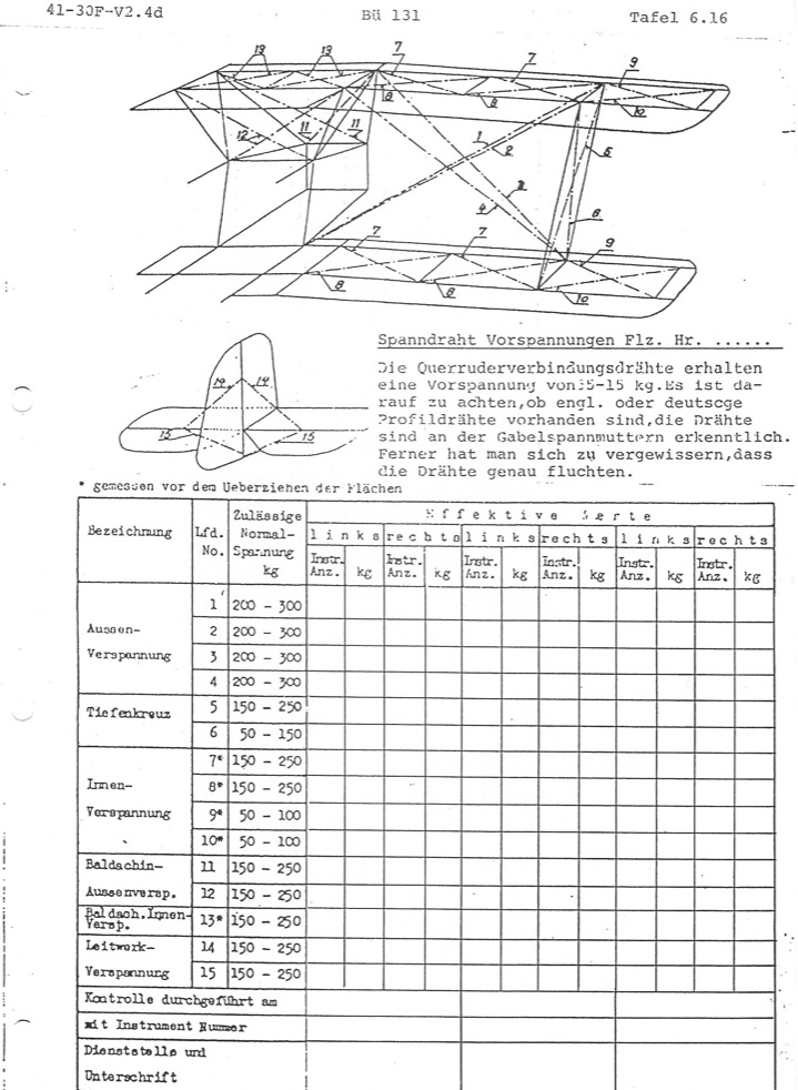
Now that the dihedral and incidence are set, the flying wire tensions can be set with a tensiometer or by using a simple fishing scale. Place the fishing scale in the center of the wire and pull until the wire deflects by the amount indicated in the table below. At that deflection, the scale should read the amount shown in the "pull" column.
This is derived from the formula F = (4DT)/L where F = pull force, D = deflection, L = length and T = tension. where:
F is in pounds
D is in inches
L is in inches
T is in pounds
Don't you just love imperial measurements?
| Wire | Designation | Length (inches) | Tension (Kg) | Tension (Pounds) | Defection (inches) | Pull (pounds) |
| 1 | Front Flying wire | 90.75 | 200 ~ 300 | 440 ~ 660 | 0.75 | 18.2 |
| 2 | Rear Flying wire | 92.00 | 200 ~ 300 | 440 ~ 660 | 0.75 | 18.0 |
| 3 | Front Landing wire | 82.75 | 200 ~ 300 | 440 ~ 660 | 0.75 | 19.9 |
| 4 | Rear Landing wire | 79.0 | 200 ~ 300 | 440 ~ 660 | 0.75 | 20.9 |
| 5 | Interplane, lower rear to upper front | 51.25 | 150 ~ 250 | 330 ~ 550 | 0.5 | 17.2 |
| 6 | Interplane, lower front to upper rear | 41.75 | 50 ~ 150 | 110 ~ 330 | 0.5 | 10.5 |
| 7 | Internal drag wires, inboard | 150 ~ 250 | 330 ~ 550 | |||
| 8 | Internal drag wires, inboard | 150 ~ 250 | 330 ~ 550 | |||
| 9 | Internal drag wires, ourboard | 50 ~ 100 | 110 ~ 220 | |||
| 10 | Internal drag wires, ourboard | 50 ~ 100 | 110 ~ 220 | |||
| 11 | Front cabane wire | 42 | 150 ~ 250 | 330 ~ 550 | 0.25 | 10.5 |
| 12 | Rear cabane wires | 26.25 | 150 ~ 250 | 330 ~ 550 | 0.25 | 10.5 |
| 13 | ? | |||||
| 14 | Top tail wires | 28.25 | 150 ~ 250 | 330 ~ 550 | 0.25 | 15.5 |
| 15 | Bottom tail wires | 26.0 | 150 ~ 250 | 330 ~ 550 | 0.25 | 16.9 |
There are a couple of interesting entries in this table I think: Firstly, the range of acceptable tensions is large. +/- 50% in some cases, so a calculator with 23 decimals is probably not required. The crossed wires at the interplane struts also have quite different tensions.
And from Joe Vasile:
The following is my technique. It has worked well for me:
I use a 4' length of aluminum angle and a "Smart Level" digital level to level the aircraft and set all the angles. This works great and produces very good accuracy.
Once the center section is rigged and all the wings are attached I set the dihedral of both the lower wings by placing the aluminum angle directly over the front spar on the lower wing running it from just inside the inter-plane struts toward the root. Place the Smart Tool on the aluminum angle and set the dihedral to between 3.6 and 3.7 degrees. This will yield 3.5 degrees once the flying wires are tightened down.
Next I set the incidence of both lower wings by placing the aluminum angle on the bottom side of the lower wing aligned directly over the rib closest to the inter-plane struts. I set the starboard wing to -0.5 degrees and the Port wing to -0.1 degrees by adjusting the wires that form the X between the inter-plane struts. This adjustment in critical to obtain hands off straight and level flying and works for my 125Hp Tigre and Hoffmann prop combo. Others may need more or less. If the plane rolls left or right on your first flight tweaking the wires between the Port inter-plane struts will fix the problem.
Next tighten the flying wires. Tighten the front smaller wire first and than the back wire. I bring both Port and Starboard flying wires finger tight first and then tighten them all 1/2 turn at a time until I get the proper tension. Until the last few adjustments whatever I do to the left side I do to the right before moving to the next wire. i.e.. Bring the port front flying wire finger tight. Bring the Starboard front flying wire finger tight. Bring the port rear flying wire finger tight. Bring the starboard rear flying wire tight...etc. This has you walking back and forth quite a bit but helps maintain overall geometry of the aircraft.
Last recheck all of the angles tighten the jam nuts install the javelins and go fly. Once the aircraft is assembled I can now dial in the rigging in about 45 min. I took me about 4 hours the first time.
Cheers,
Joe
From Albert Zeller: